Search the site...

thomas mechanical design
  • Home
  • About/Contact
  • Projects
    • Rocket Fin Jig
  • My Workshop
    • Organization
    • Mill Workbench
    • Notebooks
  • The Mitch Blog
  • Home
  • About/Contact
  • Projects
    • Rocket Fin Jig
  • My Workshop
    • Organization
    • Mill Workbench
    • Notebooks
  • The Mitch Blog

The Mitch blog

JUICERO - Brute Force and Ignorance

12/17/2017

1 Comment

 
Like many other technology-minded people, I've watched the saga of the Juicero $400 (down from $700) juice bag squeezer with amusement. buying a cup of juice in a bag for $5 seems like a bad business plan (and many others have already discussed that). I'm more fascinated with the juicero machine itself. AvE did a thorough teardown of the machine, so watch his video for the gory details. In short, the insides of the machine are a thing of beauty, and much too expensive for getting people hooked on a $35 a week juice subscription.
Ben Einstein at Bolt.io also did a detailed teardown of the Juicero, again pointing out how beautiful and totally over-engineered this machine is. He estimates the juice pack is seeing 64psi load in order to get the juice out.
Part of the failure of this whole endeavor is that the machine was so damned expensive! This was an attempt at a "razor and blades" model. Razor and blades is used many places where there's a consumable component; K-cup coffeemakers (allegedly the inspiration for the Juicero), actual shaving razors, computer printers, old polaroid cameras, some video game systems. The whole premise is that you give away the razor, or sell the coffeemaker (or printer) at a heavy loss to get people to then buy the very profitable blades (or printer ink) forever.

But if you make the machine too expensive, this doesn't work. And this thing is PRICEY! So many CNC-machined components, massive gears, thrust bearings, tapered roller bearings, dowel pins, etc. All of these things are wonderful and expensive. These are how you build one juicer, for a lab, to test juice bag  production variability. To see this sort of stuff in a high-volume production item...yeesh. Apple gets away with this in their laptops because it's an aesthetic they're going for, and they're recycling their own super-machinable castable alloy of aluminum to bring it down from "totally bonkers expensive" to merely "high end".

​The marketing of the Juicero fixated on how strong the machine was ("Able to lift two Teslas"). Is this necessary? For some historical background, when HP first went all-in on cheapo printers (to get the printers as cheap as possible to start consumers buying ink), one of its leaders stood on an older HP printer and said "The fact that this printer can hold me up means it's too expensive". The Juicero is

To get to why the Juicero provides several tons of crushing force, we need to step back and take a hard look at what the machine is supposed to do.
  • ​To crush a juice bag? No. See AvE's video above of a normal human squeezing juice out of the bag by hand.
  • To get the juice out of the bag? Yes!
  • To get the juice out of the bag in a "reasonable" amount of time? Very Yes.
​
This is where the designers went wrong. Remember, the goal is to get the juice out of the bag. A 330VDC motor running through a reduction geartrain to a massive Acme screw to put 4 tons of force onto a bag of juice, plus another massive plate to react the 4 tons of force on the other side, all adds up to brute force and ignorance. Very forceful brutality, and beautiful, blissful ignorance.

How else might this have been approached, in a clever way?
  1. Don't offer a machine at all, and have the customers squeeze the bags themselves. This has been shown to work in videos all over youtube. Redesign the bags if necessary to make them even easier to squeeze. After all, the bags are where the money is. Often the best design is not to design anything.
  2. Make a toothpaste squeezer (which is what AvE suggests in his video). At this scale, you could call it a clothes-wringer, which was a mature technology in 1905. The level of complexity goes way down. Again, the bags could be redesigned to work in a clothes-wringer, like adding barcodes to the bags so the machine can "see" how close it is to the end of the bag.
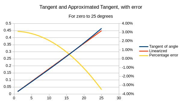
  3. Use a miniature hydraulic pump to squeeze a water bladder at 64psi against the bag. A tiny peristaltic pump (like what's inside the water flosser in your bathroom) can get to 64psi with no sweat. "But what about the 4 tons of resultant force, how are we handling that?". Build the machine to be cylindrical and then you're just talking about a pipe, which can handle 64psi very efficiently.
    1. Or as a variation, if 40psi (municipal line pressure) would get enough squeeze, make a fitting to attach a hose for the water bladder straight to the sink and just turn on the sink.
None of this addresses the zeroth question here of "How many people want to pay $35 a month for juice at home?
1 Comment

Statistical Sampling Plans - Attributes

6/2/2017

2 Comments

 
Statistical sampling plans are what you use when you're making thousands of cans of chili every hour, and trying to make sure there isn't too much ratmeat in the cans. Checking every can isn't really possible (perhaps somebody with a sensitive palate has to taste the chili for those subtle notes of squeaky meat), so what are you to do? Enter Statistical Sampling by Attributes, originally laid out in Mil-Std-105, and then updated in ASQ/ANSI Z1.4. Down below I've attached revision E of Mil-Std-105, which is the last revision in the public domain. Z1.4 revision (dash) could be considered revision F of Mil-Std-105
mil-std-105e.pdf
File Size: 2562 kb
File Type: pdf
Download File

So you break open the Mil Standard, and start going through the steps. And by "steps", I mean the standard lays out, step by step, how to establish a sampling plan. We choose a verification level of 3, which is the most stringent, and decide to test batches of chili five thousand cans at a time. From Table 1, level 3 with 5,000 cans gives us Sample Size code M.
Picture
Table 1 of Mil-Std-105E, which shows sample size codes for different lot sizes and inspection levels.
From there, we choose an Acceptable Quality Level of 0.25 (0.25% of cans can have ratmeat, because it won't actually kill​ the consumer), which by Table 2 means we will take 315 samples and will accept the whole batch as long as two or fewer samples are contaminated. We will reject the whole batch if three or more samples are contaminated.
Picture
Table 2 of Mil-Std-105E, which shows specific sampling plans for given sample sizes and AQLs.
If you're doing math along with me, you'll probably say "Hey, how does 2 in 315 get us to 0.25%?" And you'll be right that it doesn't. Not directly anyway. In table 5, the Average Outgoing Quality Limit for our inspection plan comes in at 0.44%, which means that if we test every complete batch of cans whose batch samples failed, and then throw away all the contaminated cans we find, we should have no more than 0.44% contaminated. This still isn't 0.25%...

​The missing link is that the whole sampling plan is predicated on there being a quality control system that manages the inputs. In the case of our "rats in the chili" scenario, the quality control system would be a bunch of traps, or a herd of cats. For the sorts of applications the spec was written for, the quality control system would have been based on Mil-Q-9858. Like many older military standards, it's been replaced by a bunch of different industry standards (ISO 9001 for most applications, AS9100 for aerospace, ISO 13485 for medical devices, etc.)
So this is all good if you're the chili producer, and want to keep your chili relatively rat-free. But what if you're a grocery chain, and you don't make the chili yourself, but rather put your name on somebody else's chili? Accepting 2 in 315 won't get the chili factory to do their best job, and you don't know what the factory is doing to keep rats out.

​What you can do is use a more stringent sampling plan, like what's described in Mil-Std-1916 "DoD Preferred Methods for Acceptance of Product". Mil-Std-1916 has the sort of sampling plan you might want if you were buying canned chili mac, and didn't have control over the chili factory itself. Essentially, start with all the sampling plans in Mil-Std-105, but only use the ones that reject the lots if there are any cans with ratmeat in them.
2 Comments

Neat Cam Lock Stud

5/18/2017

1 Comment

 
Picture
While assembling a flat pack desk, I found this really neat cam lock studs. Most of the connections in IKEA-type furniture uses cam lock screws and nuts. So for IKEA lock screws, the blue part here would be threaded, and there would be a recess for a Phillips head screwdriver on the stud end. This stud, on the other hand, uses a taper to to expand the blue sleeve as it's pulled.

​I don't know whether the radial compressive load into the particle board will hurt anything, but it's gotta be higher than the induced radial load from threads.

​The problems one might encounter in use are probably that these will not pull two faying surfaces into intimate contact, which a regular IKEA threaded stud will do. Provided the surfaces are already in contact, these should work pretty well.
1 Comment

Terrible Instructions - Confusion!

2/4/2017

0 Comments

 
Picture
These are instructions for a flat pack desk, and​ there's much to dislike about them. On the left hand side, we see that the unfortunate builder of this desk is instructed to assemble five separate pieces of the desk, then set them aside. In practice, this means the builder will need space not only to build the desk itself, but also space to store the pieces he/she has assembled early. This is on top of the extra therbligs needed to put down, locate, and then pick back up the pieces built prematurely.

Basically this is a pictorial version of the cautionary tale / cabinet-building episode in ​All I Need to Know about Manufacturing I Learned in Joe's Garage.​

​For the curious readers, these weren't IKEA instructions. IKEA does two things very well; instructions, and meatballs.
0 Comments

Shortcuts And Mental Math

1/4/2017

2 Comments

 
 One of my mentors gave me several books he'd found valuable as a machinist, before he became an engineer.

One is a neat book called Design and Use of Cutting Tools, by Leo St. Clair, all about cutting tool geometry. The most important factors for tool life are correct rake and relief angles, so the book describes several methods of measuring angles. Let's back up a bit:

In school you may have heard of the small angle approximation, which says that as an angle gets very close to zero radians, the sine of that angle is approximately equal to the angle. This is why the equation for the period of a pendulum that you get in high school physics has the big caveat that "this only applies at small angles". (The small angle approximation can be demonstrated with the Taylor series expansion of sine; as the angle gets close to zero, the higher ordered terms drop out and you're left with sine=theta.)

As a corollary to this, cosine equals one at small angles. This can be derived by taking the Taylor series expansion of cosine; as the angle approaches zero, the higher ordered terms drop out and you get cosine=one.

So we know that at small angles sine is about equal to theta, and cosine is about equal to one. And we remember that sine over cosine is tangent. We can then make the reasonable assumption that for small enough angles, the tangent ought to be equal to the angle. Or linear with the angle, anyway.

Back to tools: we need to measure angles, and all we've got are rulers. We could try some really fancy trigonometry (like land surveyor level stuff), but the angles are all relatively small with cutting tools, so all that small angle business still just screw up the numbers. However, Mr. St. Clair comes to the rescue with the small angle approximation. He shows that between 0° and 20°, the tangent of the angle is approximately equal to the angle (in degrees) times .018. Within this range, the tangent will be correct to within 1/3rd of a degree, which is pretty good. But since we have spreadsheets, which Leo St. Clair probably didn't have in 1953, we can double-check his math.
Picture
 What I did was plot the tangent function from zero to 25 degrees, and then plot Leo St. Clair's approximation (.018 x theta), and the percentage error. From the plot, we can see that .018 times theta is within about 3% of the real tangent for angles up to 25 degrees. So there you have it! Up to 25 degrees, you can safely linearize tangent, and all your mental math becomes much simpler.
2 Comments

Picatinny and nato rails - gd&T

11/12/2016

12 Comments

 
The MIL-STD-1913 “Picatinny” rail is present on almost all current-production AR-15s, as well as numerous other rifles, shotguns, and pistols. This rail is used to mount sights, lights, grips, lasers, and pretty much anything else that could conceivably be mounted onto a gun. In 2009, this design of rail was superseded to an extent by the STANAG 4694 NATO Accessory Rail. In the following, I’ll look at the changes from the MIL-STD-1913 rail to the STANAG 4694 rail, and explain what they mean from an engineering drawing/inspection perspective.

I’m writing this article because the existing literature I can find (the wikipedia article about STANAG 4694, and some associated presentations on the NATO website) don’t provide detail into the rationale for the change; I think we can infer some rationale for the changes. Additionally, the articles in the gun media that I can find don’t seem to understand the changes, beyond the cursory summary given on the NATO website. The datum schemes for MIL-STD-1913 and STANAG 4694 are also very novel; these sorts of datum schemes are not often seen in GD&T textbooks. Finally, we can also see how STANAG 4694 incorporates obsolescent features to maintain compatibility with the “legacy” MIL-STD-1913 rails.


THE MIL-STD-1913 "PICATINNY" RAIL

Picture
Here we can see the portion of MIL-STD-1913 that defines the profile of the rail.

Read More
12 Comments

Benchtop Mill Lever Drawbar

2/17/2016

4 Comments

 
PictureOne hand holds the spanner wrench pictured, another hand turns a wrench to loosen the drawbar, and the tool falls gently onto a foot, or other soft object.
I've had my mill (a Grizzly G0463}for several years now, and I really hate changing tools. I understand the need for changing tools (it's hard to flycut with a boring head, and it's hard to make slots with a drill) but it's a huge hassle with small mills (Sieg X2 and X3-style mills). Even with a full-sized Bridgeport (or equivalent...) it's enough of a hassle that power drawbars are installed on many/most of them in industrial settings.


First, let's walk through what makes the Grizzly such a pain for toolchanges. THERE'S NO SPINDLE BRAKE! The mill comes with a stupid little spanner wrench, which grabs holes on the spindle face. This means that you have to use one hand to loosen the drawbar, another hand to hold the spanner wrench (which wants to back out as most spanner wrenches do) and a third hand to catch your precious endmill once it drops free.

Enough people find this to be a colossal hassle that littlemachineshop  sells spline wrenches, and two different kinds of spindle locks to grab the spindle spline to prevent rotation while tightening or loosening the drawbar. I built my own spindle spline lock, which works reasonably well, rather than buy one of those linked. (I don't have any relation with LMS, and don't get any sort of sweet kickback money if you click the links.)  I made my own spindle lock, freeing up an entire hand for moving tools into and out of the collet.
Picture
Here sits my mill in all its glory. At the top of the head sits the custom spindle lock. A lip on the spindle lock hangs over the edge of the head to prevent rotation.
Picture
The 1/4-20 screw sits in the groove of the spindle spline. A lip on the end of the block grabs the edge of the head (see mark in the green paint) when the user tightens the drawbar (black hex head atop the spline)
Even with something as marvelous as a spindle lock, I still had to change collets frequently, which was still a huge pain. Take the tool out, unscrew the drawbar from the collet, put the collet back in the rack, then reverse for the new collet. (Starrett sells a stepped adaptor for its edgefinders just so machinists don't have to change collets to touch off.)

I started looking into the Tormach Tooling System (TTS), which is all based around a precision spud going into a single 3/4" R8 collet. TTS would get me away from changing collets, but I'd still have to grab a wrench and turn the drawbar to release tools. This takes less time, but it still takes time. Tormach's video below explains how the TTS spud works with the R8 collet, and gives some general background for how R8 collets work.
Tormach's own mills have an optional power drawbar, wherein the drawbar is tightened against Belleville washers. The drawbar is released when a pneumatic cylinder presses the washers flat. This system works well, and many people have done similar things (hoss machine's power drawbar is very well-known among hobbyists running Sieg-type mills).

Using pneumatics is fine and dandy, and how many commercial CNC machines work. To do this I'd need to buy an air cylinder ($$) and also an air compressor ($$). This seems like a terrible plan to me, since I don't have an air compressor, and don't really want one just to change tools. They're loud, big, and this would be the only thing I run with it. Maybe someday, when I own my own house and can put a compressor into a soundproof enclosure.

With pneumatics out of the picture, I started looking into levers, and toggle links. In part this was because nobody seemed to have (or want to use) a big enough air cylinder to act directly on the drawbar-everybody was using a lever system to increase the force. I saw what SDM Fab did with a lever drawbar and thought that that was a good path forward. Their lever system has a detent to hold the collet open. The downside for my application was that it looked like a pain to make on a manual mill, and it was way bigger than anything I think I need. I don't have the machine rigidity of a Tormach and thus can't put as much useful force into the tool, so there's no need to grab onto the tool quite as strongly. Also there are numerous parts which will cost me money, and also the mysterious "hydraulic intensifier".

So what I started thinking about was cams. Instead of using levers, a cam will give greatly amplified force in comparison to a lever, and is self-locking in many cases. This gets me away from detents, and also gets the size down.
Picture
The hex head and spline feature are the same as pictured on the existing mill. The yellow base plate will sit on top of the green top piece of the mill.
The general notion here is that the entire assembly (all the colored bits) will slide onto the top of the mill (not shown), and I'll pull down on a lever attached to the cam (blue). The friction between the cam and the hex head of the drawbar will pull the baseplate (yellow) into contact with the spindle splines. Additional pulling on the lever will rotate the cam and drive the drawbar down, compressing the belleville washers and releasing the collet. This design is the culmination of several years of ruminating and sketching; it's pretty simple, doesn't add extra weight to the head (very important for a manual machine), and doesn't put axial load on the spindle (not that critical in the X3-type mills, but very good for other mills).

Much like most fixtures I've ever designed, this thing is not pretty. I'm using all aluminum (6061 that I have handy for pretty much everything, and relatively hard-wearing 2014 for the cam itself, again what I've got handy) with socket head cap screws and dowel pins holding it all together. Dowel pins and screws are a great way to put together fixtures, because they're very easy to analyze. The tensile/clamping forces I need drive the size and quantity of the SHCS, and the shear forces drive the size and quantity of the dowel pins. This is how IKEA does it - screws to clamp, dowels to take shear, and never the twain shall meet.

There are a few risks I see with this design. 
  • Bending/deflecting the drawbar while camming open or closed, possibly causing problems. The frictional force is proportional to the downward force so there's probably a critical relationship between spring stack height and the cam to drawbar friction coefficient. I can calculate that if I start to worry too much.
  • Wearing down the cam surface over time. This may smooth/burnish the surface at first, but getting aluminum shavings down into the works of the spindle can't be good. If needed I could remachine the cam out of something harder (aluminum bronze, as an example) but that would be more expensive too. So we'll just wing it.
  • Cracking the top cover of the head. It's a casting, and not super thick. I have a hunch that the greatest load will be while compressing the springs (as opposed to releasing them) so if my yellow baseplate extends to the edge I should be good. Plates are really weak in bending, but if you can get the load out to the edge, the edge is much stronger in compression for the same force. This is why we stack the same sized moving boxes on top of each other when we can.

I'll get into the nitty-gritty of this design and what led to it in future posts, especially since I just noticed I don't have the right size drills for the dowel pin reamers I'm going to use.
4 Comments

what's all this thread pitch business?

2/10/2016

1 Comment

 
If you've ever bought SAE (American) fasteners, you've no doubt seen the initials "UNC" and "UNF". What do they mean? Which is better? And what are "UNRC" and "UNRF"? Read on to find out!
Picture
So many weird acronyms on our Holo-Krome selector.

Read More
1 Comment

Soldering Station

7/26/2015

1 Comment

 
I recently helped my lovely wife install a new radio into her car. Taking the old radio out involves some brute force and ignorance, greatly aided by the Master Sheet that Crutchfield emails along with the radio. For some reason, every OEM radio I've seen has an extra screw that serves only to complicate removal. I'd say this is an anti-theft feature, but who steals the crappy stock radio?

The most fun part of installing a new radio is soldering the new radio's plug to the adapter that comes with the install kit. The radio manual helpfully suggests splicing into the car's wiring harness, which is insane.

What makes soldering such a pain is having to dig out the soldering iron, and solder (stored in different places, of course) and then find a flat surface to do the soldering.
I took a scrap piece of MDF board (from a super nice knockdown desk) and stuck in a threaded insert, then used a threaded knob to hold on a roll of solder. The actual soldering iron is held stationary using a bunch of wood screws and some zip ties. We'll see how well the zip ties last, but if they're good enough for auto repair they should be dandy in a silly solder board. The final touch is a scrap piece of plywood and part of a paint stir stick to keep the cords from flopping around getting broken.
I still need to add a helping hand and maybe a spot for shrink tubing.
Picture
Picture
1 Comment

Milling a slot in a motorcycle engine

7/19/2015

6 Comments

 
This post is a bit of a blast from the past (March 29, 2014 to be exact).

My brother had a Honda CB-350 motorcycle, which he was in the process of restoring. He got a new timing chain tensioner for the overhead cams, but the original timing chain slot in the engine head wasn't wide enough. That's where I came in. We fixtured the head on the mill, which was very simple, if not very easy.
Picture
Cutting the slot.
The head didn't have an entirely flat surface on the bottom, which is why you can see it's sitting on two clamp straps. I was probably picking up bosses originally in the casting, though I can't remember now. Fortunately the flat surfaces available were parallel to the bottom of the head, or I'd have needed a machinists jack or two. The block did have two very convenient through-holes, which I stuck studs through and then tightened down with nuts, visible immediately to the left and right of the spinning endmill in the picture. The through-holes weren't in an ideal spot though, so I used regular step blocks (a LOT of them, as you can see) to hold down the back end of the block. I didn't need to use any stud couplers though, because clamping studs are always longer than you need for some reason.

The slot started out at .651 wide, and we needed to open it up to .800, to a depth of 1.50.   I also measured the distance from each side of the slot to the combustion chamber dish and found that the slot was .025 closer to the right head. I was using an 11/16 endmill (.691), so I did some math and worked out that I needed to cut .042 into the right side, and .067 into the left side.

I zeroed the X-axis leadscrew, came over .042, widened the slot .800 deep, then locked the X-travel, took up the backlash, rezeroed the leadscrew, and came backward .109 to finish the job. The tensioner fit perfectly, and the bike's running today as far as I know.
Picture
Both photos by Max Thomas
6 Comments
<<Previous

    Archives

    February 2016
    July 2015

    Categories

    All
    Engines
    Fasteners
    Machine Design
    Mechanical Design
    Milling
    Projects

    RSS Feed

Proudly powered by Weebly