The MIL-STD-1913 “Picatinny” rail is present on almost all current-production AR-15s, as well as numerous other rifles, shotguns, and pistols. This rail is used to mount sights, lights, grips, lasers, and pretty much anything else that could conceivably be mounted onto a gun. In 2009, this design of rail was superseded to an extent by the STANAG 4694 NATO Accessory Rail. In the following, I’ll look at the changes from the MIL-STD-1913 rail to the STANAG 4694 rail, and explain what they mean from an engineering drawing/inspection perspective.
I’m writing this article because the existing literature I can find (the wikipedia article about STANAG 4694, and some associated presentations on the NATO website) don’t provide detail into the rationale for the change; I think we can infer some rationale for the changes. Additionally, the articles in the gun media that I can find don’t seem to understand the changes, beyond the cursory summary given on the NATO website. The datum schemes for MIL-STD-1913 and STANAG 4694 are also very novel; these sorts of datum schemes are not often seen in GD&T textbooks. Finally, we can also see how STANAG 4694 incorporates obsolescent features to maintain compatibility with the “legacy” MIL-STD-1913 rails.
I’m writing this article because the existing literature I can find (the wikipedia article about STANAG 4694, and some associated presentations on the NATO website) don’t provide detail into the rationale for the change; I think we can infer some rationale for the changes. Additionally, the articles in the gun media that I can find don’t seem to understand the changes, beyond the cursory summary given on the NATO website. The datum schemes for MIL-STD-1913 and STANAG 4694 are also very novel; these sorts of datum schemes are not often seen in GD&T textbooks. Finally, we can also see how STANAG 4694 incorporates obsolescent features to maintain compatibility with the “legacy” MIL-STD-1913 rails.
THE MIL-STD-1913 "PICATINNY" RAIL
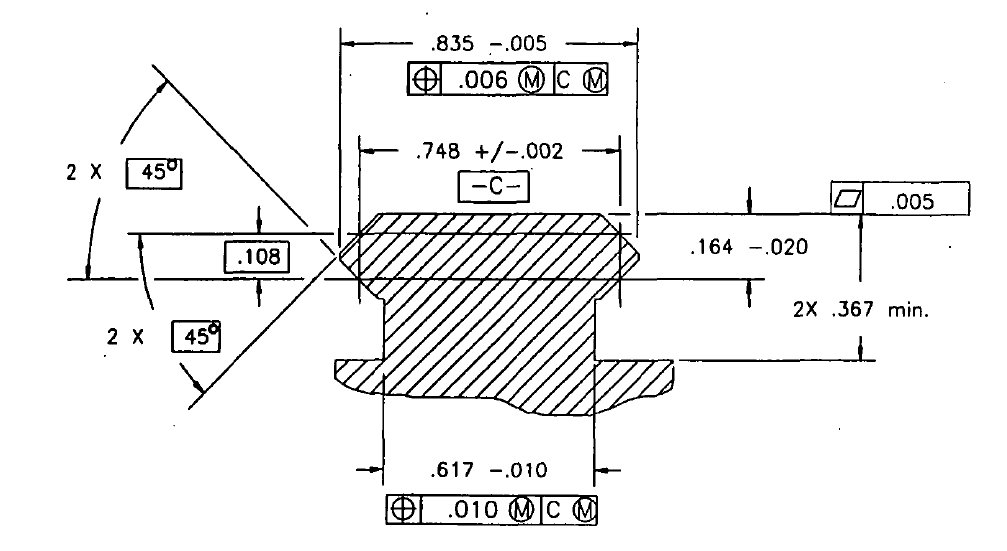
Here we can see the portion of MIL-STD-1913 that defines the profile of the rail.
As I mentioned earlier, Picatinny Rails are everywhere. Scopes, grips, lasers, lights, sights are all made to mount to them now, as they’re the de facto standard on guns. Of course, we can’t about the “de facto” standard without talking about the actual standard, MIL-STD-1913.
Let’s start with the mathematical description of Datum C
On a drawing, Datums are how interfaces are defined. For the Picatinny Rail, the Datum is what is theoretically the interface between the Rail itself and the sights.
Let’s start with the mathematical description of Datum C
On a drawing, Datums are how interfaces are defined. For the Picatinny Rail, the Datum is what is theoretically the interface between the Rail itself and the sights.
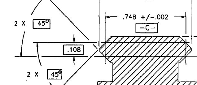
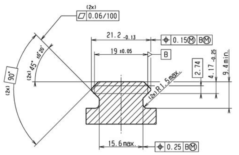
For most GD&T users reading this, their reaction is going to be “What the heck is going on here!?”. We have three separate Basic dimensions that aren’t referenced in any Feature Control Frames, which seems odd. We also have the Flag for Datum -C- attached to a size dimension, but this dimension isn’t really a Feature of Size (since it’s not two opposed surfaces). Let’s step through this bit by bit.
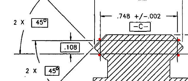
What’s going on here is that the basic .108 dimension is defining tangency points by which the datum can be defined. Two sets of tangency points (red dots) which will be oriented vertically, and spaced apart vertically exactly .108 inch. These two sets of points will move inward in pairs toward the angled surfaces until all four points are touching. When touching, the points must be .748 +/- .002 inch apart. There is no real form control on the angled surfaces themselves because they are defining the datum by their relationship (.748...). If all the surfaces were canted inward (say 47º, instead of 45º) the relationship of the angled surfaces would potentially make the two sets of points NOT enter contact until they were less than .748 apart, which would violate the size requirement for our Datum arrangement. The important distinction here is that mathematically the angles of the surfaces are irrelevant, as long as the surfaces move inward or outward to maintain the .748 +/-.002 dimension. These four points coming into contact will constrain three degrees of freedom; up/down, left/right, and rotation relative to the axis of the rail. (To get the total of 6 degrees of freedom needed to fully constrain a sight/light/mounted object, rotation up way from the rail and sideways away from the rail are constrained by either a longer single mount or by two mounts spaced apart; constraint for forward/aft movement is through friction in the mount and through recoil lugs in the rail slots).
Let’s work our way through the clearance dimensions:
Let’s work our way through the clearance dimensions:
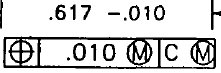
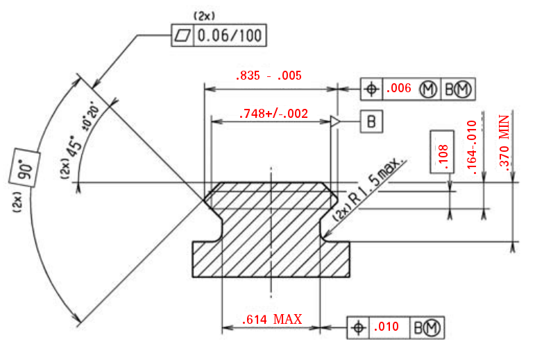
At the bottom of the drawing, we have the size and position of the base of the rail. The width of the bottom is given as .617-.010 (.617-.607) with a true position callout underneath. We know that the bottom of the rail needs to be strong enough to hold everything in place, but still narrow enough to stay out of the way of the rail grabber of whatever we’re attaching. We have here true position of .010 at Max Material Condition, relative to Datum C at Max Material Boundary. This means that the bottom can shift left and right .010 relative to Datum C (the rail), and the MMC modifier means that as the bottom shrinks from .617 down to .607, it can shift left and right an amount equal to the shrink; this is often called “Bonus” tolerance. In sum, the total potential width that the bottom can occupy is .627, which is its max width at MMC (.617), plus its tolerance at MMC (.010).
This total potential width used (.627) is called the Virtual Condition, which is a very important concept in GD&T. Functionally, this means that we can know the maximum space that the base can take up, so we can design a rail grabber that doesn’t interfere with it. Datum C is referenced at Max Material Boundary (MMB), which means that as the features that comprise Datum C depart from their Max Material Boundary (as the beveled surfaces of the rail shrink inward from their max size) the bottom can shift as well; this is called “Datum Feature Shift”, and it is not quite the same thing as Bonus tolerance, though it has somewhat similar effects. Datum Feature Shift might be best explained as allowing the feature to rattle around as the Datum Feature shrinks; if your foot shrinks, then your shoe can move around on your foot before your toes are crushed.
This total potential width used (.627) is called the Virtual Condition, which is a very important concept in GD&T. Functionally, this means that we can know the maximum space that the base can take up, so we can design a rail grabber that doesn’t interfere with it. Datum C is referenced at Max Material Boundary (MMB), which means that as the features that comprise Datum C depart from their Max Material Boundary (as the beveled surfaces of the rail shrink inward from their max size) the bottom can shift as well; this is called “Datum Feature Shift”, and it is not quite the same thing as Bonus tolerance, though it has somewhat similar effects. Datum Feature Shift might be best explained as allowing the feature to rattle around as the Datum Feature shrinks; if your foot shrinks, then your shoe can move around on your foot before your toes are crushed.
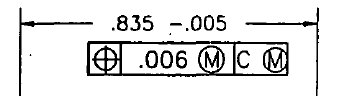
At the top of the drawing, we have the size and position of the outer edges of the rail. The width of the rail is given as .835-.005 (.835-.830), with another true position callout underneath. We can see right away that the size tolerance here is tighter (-.005, instead of -.010). This is most probably because the outer edges of the rail can’t stick too far out or they’ll get caught up in the angles of the grabbers. They also can’t come in too far or the surfaces defining Datum C will disappear. The outer edges of the rail also have a tighter position tolerance, (.006 instead of .010) again at MMC, and again reference Datum C at MMB.
Finally on the right-hand side of the drawing, we have the height of the top point of the rail, with respect to the surface below the bottom of the rail. This is called out as a Minimum dimension, which makes sense here; the rail can be as tall as we’d like, but we need a minimum clearance for the grabbers.
mounts to use the mil-std-1913 "picatinny" rail
Now that we’ve reviewed how the rail is designed, let’s look at how some common mounts actually interact with the rail.
How does this differ from the mathematically ideal mount?
A mathematically ideal mount would have four rollers/cylinders, arranged in pairs vertically so that their tangential contact points with the rail's beveled surfaces were exactly .108 apart. The pairs of rollers would translate inward toward one another, and mate up with “sufficient” force for all in-spec rails.
There are some problems here though. Since the four beveled surfaces aren't controlled as far as their angles, the contact locations for any given side will shift closer together as the angles decrease, and farther apart as the angles increase. The magnitude of this shift will be proportional to the radius of the rollers. We can minimize this shift by decreasing the rollers' radii, but this will increase Hertzian contact stress (the limit here would be a sharp edge, which has theoretically infinite stress prior to the rail surface being dented/damaged). A narrow radius also allows for possible damage of the mount, which will make all this mathematical perfection irrelevant anyway. (For comparison here, think about how hard it is to put a dent into a trailer hitch ball, compared to trying to nick the edge of a knife).
So while we can imagine a mount that would be mathematically ideal for attaching to a Picatinny rail, we can't build one that will work well in practice. It's much easier to define a datum mathematically than it is to physically interact with one; this is a hard-learned lesson for most GD&T users.
Why does a mathematically ideal mount matter?
I keep talking about a mathematically ideal mount, but why do mathematically ideal mounts matter when we live in the real world? There's a joke about how physicists calculate milk production, and it ends with "first assume a spherical cow”. When we engineer things, we are making simplifying assumptions, which mean that our answers are only as valid as the simplifying assumptions.
1 MOA shift means what over a 4-inch long rail? Tangent of 1/60 deg (1 MOA) is 0.00029, meaning 1MOA shift equates to .0012 inch shift over 4 inches (.00029 x .4). That's one third the thickness of a sheet of printer paper (.003-.005 thick). This means that it takes very little change to move the point of impact when removing and reinstalling a scope.
To make sure the scope goes on the same way every time, we can can do many different things.
We can make sure that the scope mount grabs the rail with the same force in the same way every time. As the scope mount grabs the rail, it will bend slightly. (The rail itself will crush inward ever so slightly as well, but that effect is very minor in comparison.) If we can make sure that the mount grabs the rail with the same force every time, we can make sure the scope mount bends the same way every time, and the scope will be in the same place relative to the rail. Springs can help with this (like the Bobro mount), as can adjustment (like the LaRue mount), or consistent torque on mounting screws (most screw mounts, also the Aimpoint mount with the torque nob).
We can also make sure that the scope mount attaches to the rail in the same spot every time. The rail will be pretty similar in cross-section at different points, but it won't be exactly the same. This means that our methods above of getting the same force will be hindered somewhat, because our adjustment methods won't work as well. The elastic in a fat guy's sweatpants will grab him about the same within certain waistline limits, but it won't work as well if the fat guy loses a lot of weight. (It should also be pointed out that the rails' straightness tolerances are usually such that zero will be lost just by moving the mount forward on the rail.)
The NATO Rail (STANAG 4694)
Enter the NATO Accessory Rail (STANAG 4694). This is a rail designed to solve the problems of the Picatinny rail, while still being backward compatible with it. First, let’s look at the dimensioning of the NATO rail itself.
The basic shape of the rail looks similar enough. But there are these pesky metric dimensions where we used to have inch dimensions. So below I’ll inch-icize (anglicize?) the STANAG drawing so we can get an apples-to-apples comparison of the dimensions. What we’ll see is that not all of the dimensions are the same.
Now let’s see the Picatinny Rail one more time…

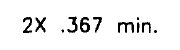
In comparison to the MIL-STD-1913 cross-section, the biggest change here is that the datum is setup differently. We still have .108 basic height for our two sets of point contacts, and the point contacts are still .748 +/- .002 apart from each other. However, now the angled surfaces are controlled with an angular tolerance (45° +/- 20’); recall that for the Picatinny rail, there wasn’t any control of what angle the surfaces were to each other. This by itself solves most of the potential problems of the Picatinny rail system.
The other major change is that the distance from the bottom pair of contact points (on the bottom angled surface) to the top face now has a tighter tolerance. It used to be +000 / -.020, but now it’s +.000 / - .010, which is half of the tolerance. The bottom angled surfaces now also have their own form tolerance (flatness .003 / 4.000), which was not present on the Picatinny spec.
The top surface no longer has explicit form control (the Picatinny spec has flatness .005), but the distance from the bottom angled surface contact up to the top face has a much tighter tolerance, so I'll argue that the NATO rail is tighter nonetheless.
Most of the clearance dimensions are the same. The width of the outer edges of the rail is identical. The clearance from the top surface of the rail to the bottom of the base has increased by .003, which is backward compatible (since it will allow all Picatinny mounts, and then some), but is also so close as to be meaningless in practice (.003 is the width of a sheet of paper). The actual width and virtual condition of the base is functionally very similar; .010 position tolerance, with datum feature shift. The difference is that the Picatinny rail is positioned at MMC, and thus has bonus tolerance available as the width of the base shrinks (creating more clearance); the NATO rail has no minimum width of the base (which also creates more clearance). Minimal practical difference, as I suspect that most NATO rails will be manufactured with much more clearance than would be allowed by the Picatinny spec.
Specifying the “Preferred” mounting arrangement
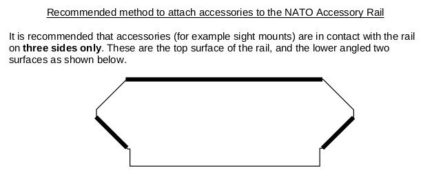
Probably the biggest change between MIL-STD-1913 and STANAG-4694 is that STANAG defines the mounting method. It's a good change as it can be argued that STANAG is really defining not just the rail itself, but the system of attaching to it. It's sort of an an interface control document, and ICDs generally control both sides of the interface. It's also a statement that the datum scheme (and thus the interface scheme) in MIL-STD-1913 was a failure in its implementation at least.
This is the mounting arrangement most commonly used anyway, so the practical effects of this change are pretty minimal.
This mounting arrangement does tie in with the changes to the dimensioning. The underside bevels now have form control, which is good as there will be more consistency in what the grabbers will see. The distance from the tangent points on the underside bevels to the top surface is now much tighter; for mounts that touch the top surface and the underside bevels, they'll be much more consistent. It should be mentioned that the preferred mounting arrangement doesn't involve the topside bevels at all; they're still present mainly for backward compatibility with “correct” MIL-STD-1913 mounts, as rare as they are.
 RSS Feed